Overview
Duration: Jul. 2017 - Oct. 2018
This project was designed for the Time-limited Airdrop Project in the 2018 China Aeromodelling Design Challenge competition (Participants of CADC came from nearly 100 universities in China). Our three flight groups won the first 🥇, second 🥈, and third 🥉 places, thereby setting the best records in history. As the leader of the composite group, I led six members to complete the production of the D-box structures, wing spars, ailerons, and fairings of six aircrafts for each of the three flight groups.
Achievements
This competition requires each team to design and manufacture an aircraft which should satisfy the following requirements:
-
Driven by an internal combustion engine
-
Remotely controlled to take off from a specific area
-
Carry an amount of water as load
-
Can release the load after flying to a certain height (18m) above the release area.
The aircraft should return to the field safely and circulate until the end of the race (600s). The team that carries the heaviest load and drops the load most accurately will win. Each university shall have a maximum of three flight groups, and each flight group shall have a maximum of two models in the competition.
Please refer to the complete rulebook (CN) for more information.
Three-view drawing of the airplane
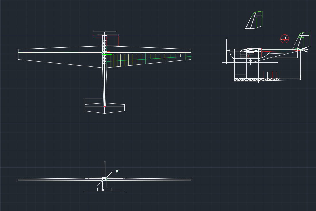
Basic design parameters of our aircraft are as follows:
| Design parameter | value |
|---|---|
| Maximum load | 24 kg |
| Maximum take-off weight | 27.5 kg |
| Ideal flight speed | 15 m/s |
| Maximum wing load | 127 kg/m2 |
| Static thrust-weight ratio | 0.35 |
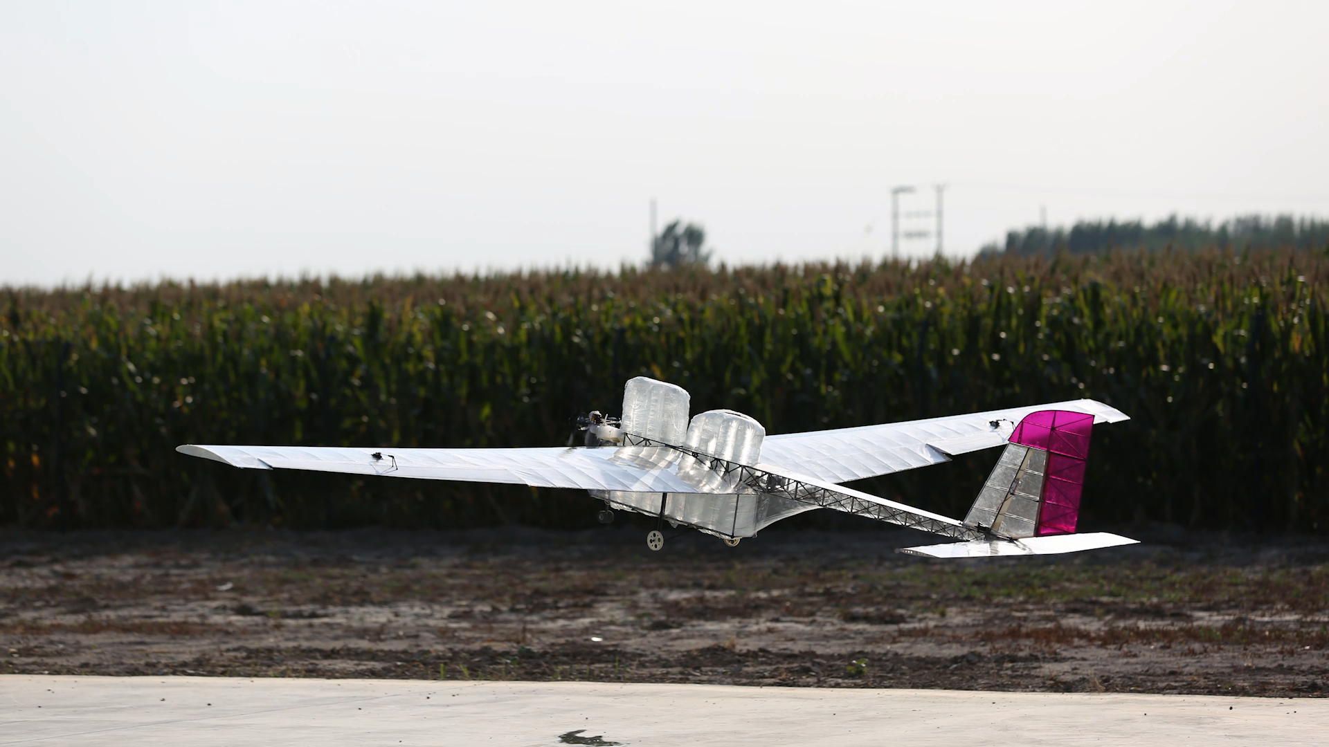
The following video is an overall introduction of the aircraft:
This video is a recording of the CADC competition. (Since there were three rounds in total and each round had three teams, we compiled a great deal of video footage. To limit the excessive length, only one video appears here.)Division
All members come from the Beihang Aeromodelling Team. The team was divided into five groups, responsible for composite materials, wings, fuselage, power, and electricity.
Composite material team members: LI Jinjie (team leader), SHI Tailong, XU Yingjian, YIN Qian, MA Guoquan, SUN Xiaozhen, LI Yunjin
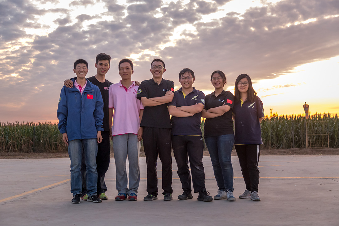
Instructors: Prof. WAN Zhiqiang, LI Yongxin, WANG Funan
An introduction of my work
My task was to lead the composite team to complete the fabrication of the composite beams, D-box, ailerons, and fairing. In addition to completing these production tasks, my main contributions included:
- Changing the grain of glass fiber from straight to twill to conform to the direction of maximum shear stress, according to the material mechanics theory I learned.
- Sourcing a specialized Ukraine-made carbon cloth from a European glider BBS, which weighed merely 30 g/m2 in order to meet both the stress and the weight requirements.
- Designing the testbed based on the course experiment and manufacturing test pieces.
- Solving the problems in the production process and optimizing the production efficiency.
Based on the test, the new D-box was able to increase the torsional resistance to 2.61 times what it was before without significantly increasing the weight. This technology effectively solved the problem of torsional stiffness of the high aspect-ratio wing and thus, ensured the outstanding performance of the aircraft.
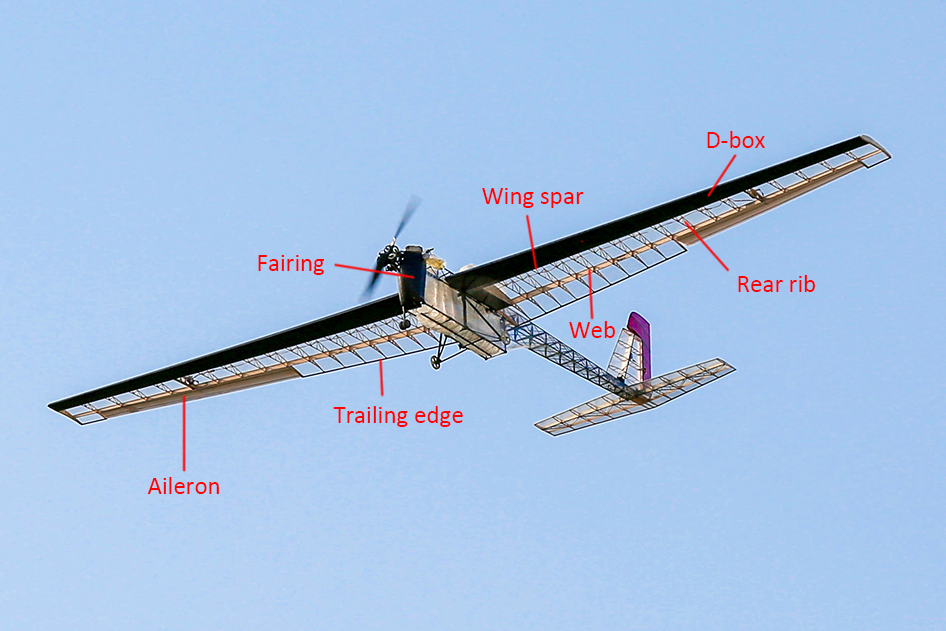
Wing
The wing structure is shown in Figure 1. Both the left and right wings are single-spar structures. Each wing is designed in two parts: the front half consists of a spar, the front half ribs and the skin form a “D” shape closed chamber structure (D-box), as shown in Figure 2; the second half consists of balsa wood ribs, trailing edge and heat-shrinking film skin. The wings and the fuselage are connected by aluminum pins and the secondary pins.
| Figure 1. Wing Structure |
|---|
 |
| Figure 2. The D-box structure |
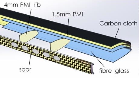 |
Material Selection:
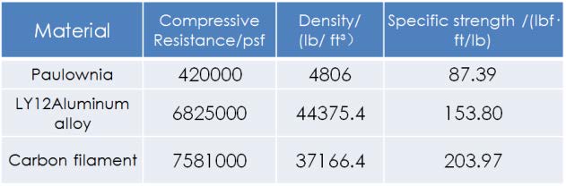
The spar bears most of the bending moment and shear force of the wing. We designed a sandwich structure to reduce the weight of the spar. The most suitable material for flanges to withstand axial force is selected by calculating and comparing the specific strength among wood, metal, and carbon filament (Figure 3). The strength of carbon filament was measured by static testing, and we therefore selected carbon filament.
| Figure 3. Properties of Different Materials |
|---|
 |
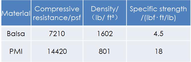
The web of the spar is mainly subjected to shear. Moreover, a variety of woods and PMIs can be used, as shown in Figure 4. PMI was selected as the spar web material.
| Figure 4. Web Strength Comparison |
|---|
 |
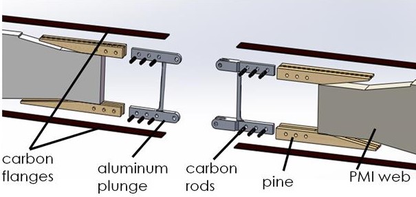
The spar structure is shown in Figure 5. Abutting aluminum pins are respectively fixed at the two wing roots and the fuselage. The aluminum pins and the pine are connected by carbon rod, and then bonded to the web, and the outer flanges are covered to ensure the connection strength.
| Figure 5. The spar structure |
|---|
 |
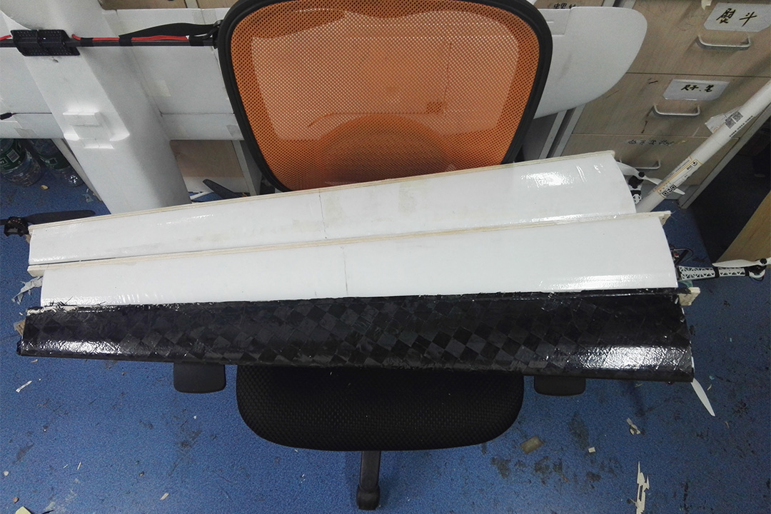
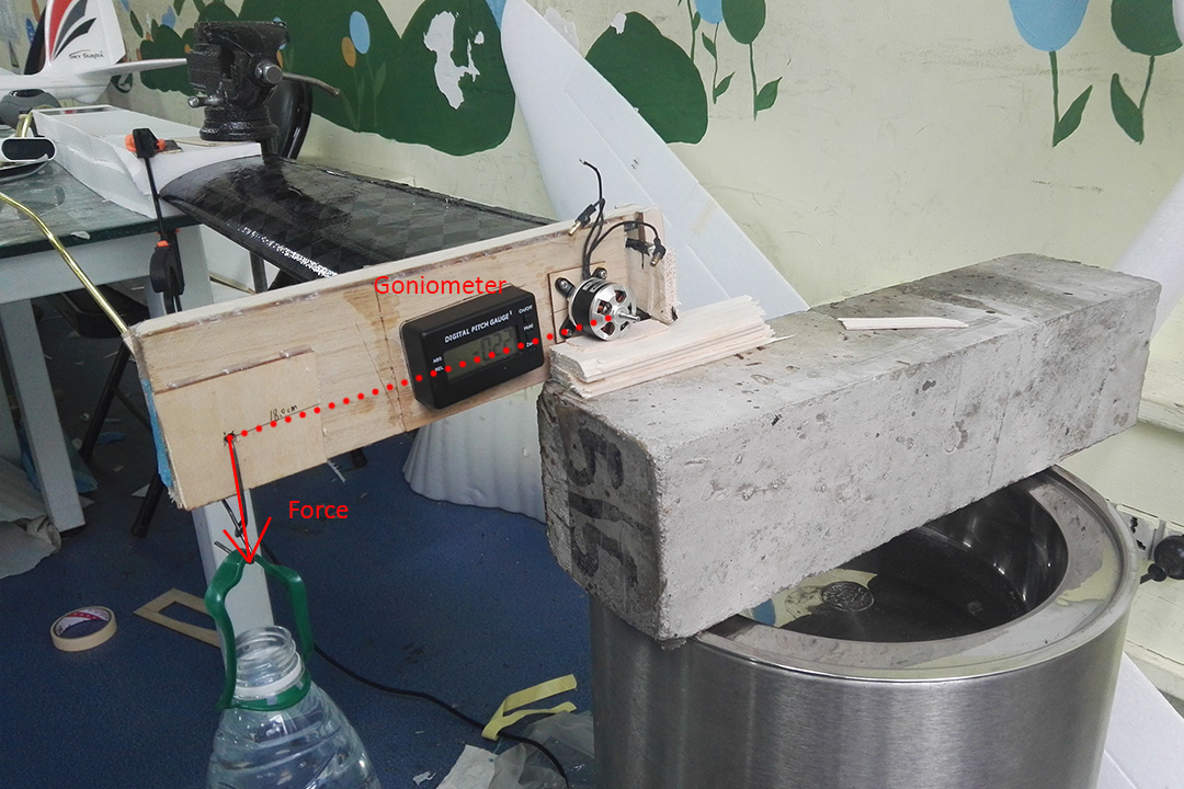
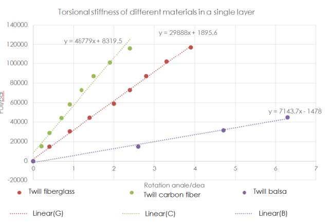
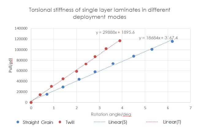
The D-box and the skin must withstand substantial torque. The torsional stiffness of the glass fiber skin under different expansion modes and the twill expansion under different materials of monolayer were measured experimentally. I designed and implemented this experiment according to the torsional stiffness experiment in the course of material mechanics (Figures 6, 7). The higher the slope, greater the torsional stiffness. Therefore, according to the results (Figures 8, 9), we chose twill carbon fiber as the D-box skin material. As the strength of the D-box was sufficient, the rest of the skin was made of heat shrinkable film in order to prevent signal shielding and reduce costs.
| Figure 6. The experimental models | Figure 7. Torsional stiffness test |
|---|---|
 |
 |
| Figure 8. Torsional Stiffness of Different Expansion Modes | Figure 9. Torsional Stiffness of Different Materials |
 |
 |
The wing in 2017 and in 2018 are shown in Figure 10 and Figure 11 for comparison. Carbon fiber is heavier, but the greater torsional stiffness reduces the number of ribs, resulting in only a slight increase in the overall weight of the wing.
| Figure 10. The wings of the 2017 aircraft | Figure 11. The wings of the 2018 aircraft |
|---|---|
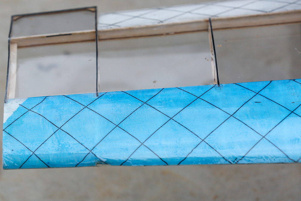 |
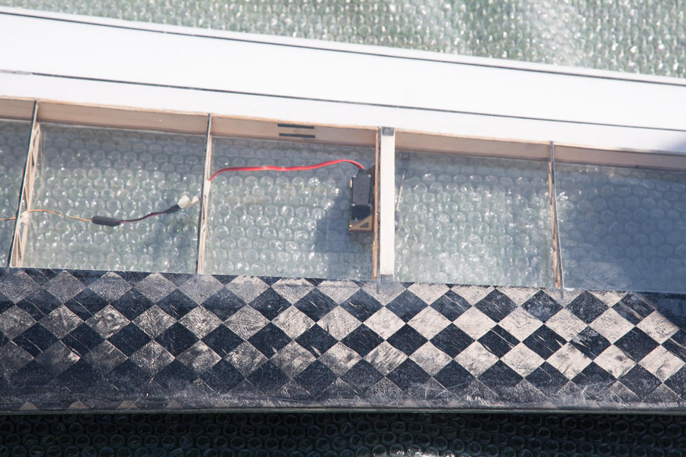 |
| Linear fiber glass, k = 18684 | Twill carbon fiber, k = 48779 |
Ailerons and Fairing
The XPS ailerons were shaped by XPS CNC thermal cutting, and glass fiber was laid on the surface as reinforcement. The XPS mold for fairing was carved by CNC milling machine, and the production process of fairing was similar to the skin of D-box. Please read the Techniques section for more information.
Techniques
PMI foam was polished and molded, with aluminum pin bonded, and a thin carbon sheet was pasted at the bonding site as the reinforcing web. Then, carbon fiber wires soaked in resin were laid on the upper and lower surfaces. After curing, Kevlar was tightly wound to prevent the flanges from losing stability and foaming, as shown in the first picture of Figure 12.
The mold was carved with CNC. Then the carbon fiber cloth was soaked in the resin and put into the mold together with PMI to be vacuum-cured, and finally the skin was formed. Loading the skin into the wing spar and rib and closing the mold, the D box was finally formed.
| Figure 12. A Beam, the soaked PMI and carbon fiber cloth, and the closed mold |
|---|
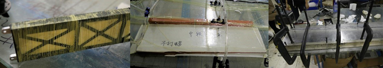 |
The plane’s wing of the Beihang Aeromodelling team participating in the 2019 SAE Aero Design (west) also uses the same D-box structure and won the first place in the advanced class overall award. 🏆
In this experience, I exercised my hands-on ability and realized my dream of making an airplane. More importantly, we worked as a team to achieve our collective goal; our journey together was truly unforgettable.