Requirements
Duration: Feb. 2018 - Jun. 2018
Design and manufacture a constant temperature control system that can be set to a specific temperature:
- Set the temperature in grades (at least three)
- The range of heat is from 50 to 100 degrees, and the error should not exceed ±5 degrees. (Score according to the accuracy)
- Use a cellphone to set and display the temperature.
- Powered by 220V AC.
Achievements
We shot this video to present the functions. Enjoy!😃
Division
LI Jinjie (Team leader) :
Designed, simulated, and tested the MCU and the analog PID control circuits; measured the PID parameters; drew the PCB board; programmed the MCU to drive the whole system; designed and manufactured the tank; prepared for the defense.
LEI Tongtong :
Designed, simulated, and tested the temperature measurement, button, display, and PWM circuits; ensured calibration of temperature measurement; soldered circuit boards; selected and purchased come components.
ZHAO Qian :
Designed, simulated, and tested the power supply and the relay drive circuits; selected and purchased the heating and cooling modules; drew the PCB boards; manufactured the entire system.
YANG Manxin :
Programmed an Android app and a WeChat Mini Program; soldered circuit boards; tested the display circuit; measured the PID parameters; designed and manufactured the tank; prepared for the defense.
Instructor : Associate professor TANG Yao
Our plan
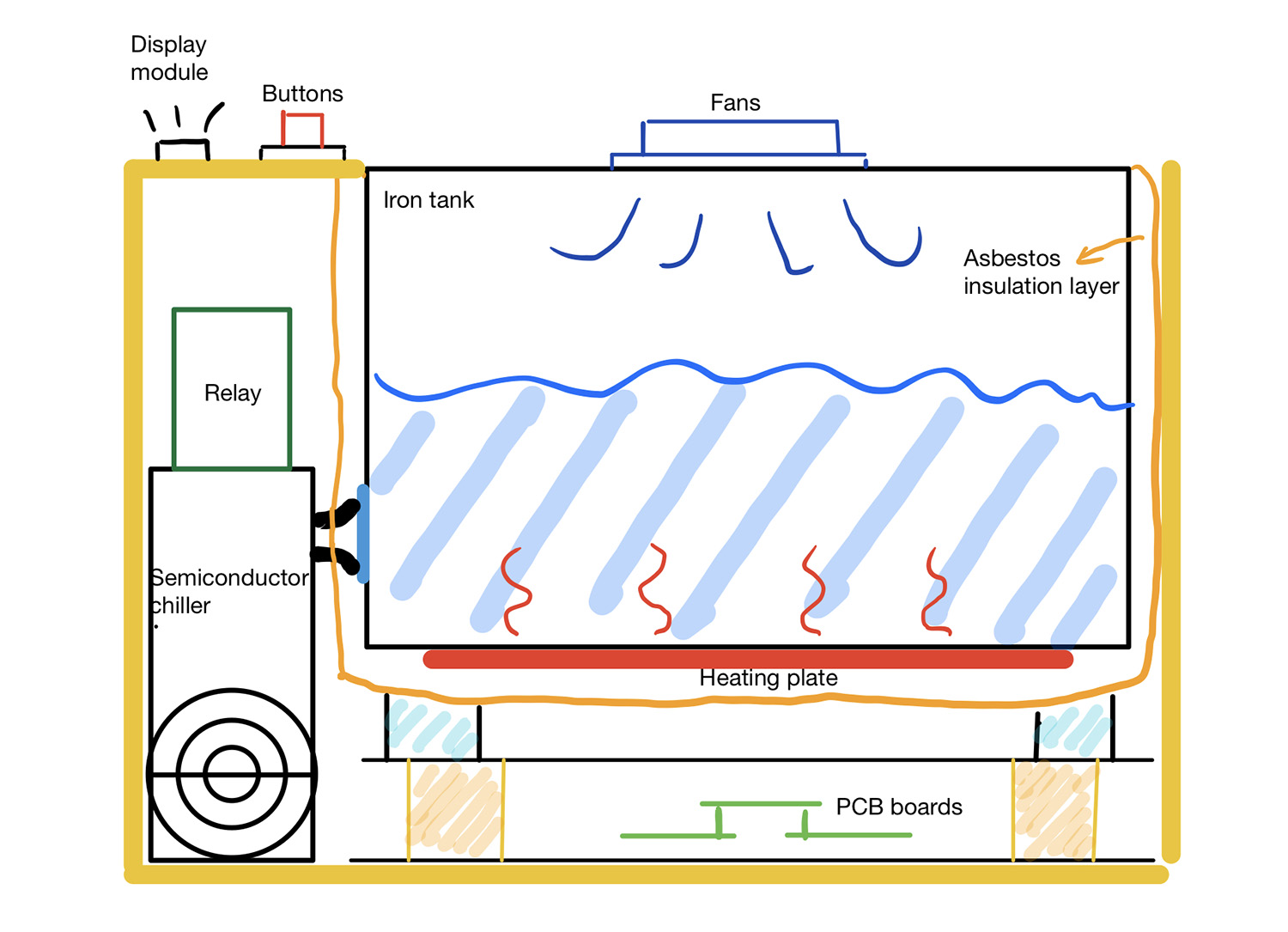
The target temperature can be set using an Android cellphone or using buttons. There are three buttons on the top of our tank: ‘SET’, ‘UP’ and ‘DOWN’. To set the temperature, press the ‘SET’ button, and the digital tube will flicker and display the target temperature. Continue to press the ‘SET’ key to select the digit, and adjust values through the ‘UP’ and ‘DOWN’ keys. After selecting the temperature and stopping operation for three seconds, the digital tube will display the current temperature and the device will warm up or cool down to the target temperature.
Internal size: 300*200*150mm
Accuracy: < ±2℃ (Depending on the environment and how much water is loaded)
Adjustment time: Approximately 5min (Depending on the environment and how much water is loaded)
Simulation: Multism
PCB design: Altium designer
MCU program: STM32CubeMX, Keil 5 👉See the program here.
Implementation
-
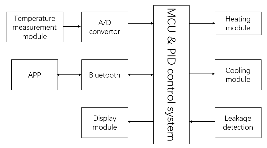
MCU & PID control system
Function Name Number Display circuit IO 7 Button circuit IO 3 Temperature measurement ADC 2 DS18B20 IO 1 PWM wave generate circuit IO 4 PID circuit DAC/ADC 2/1 According to our design requirements, we chose STM32ZET6 core board as our MCU.
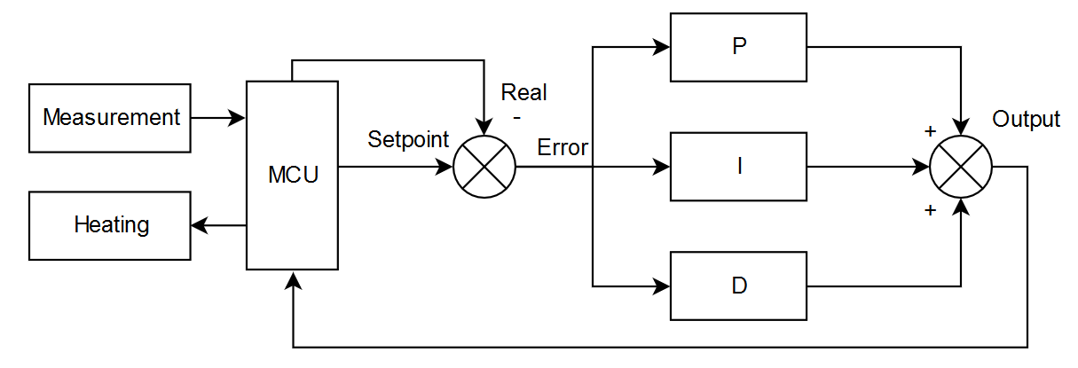
In this course, the proportion of analog circuits is a scoring factor, so we used an analog PID circuit for temperature control, as the following pictures shows.
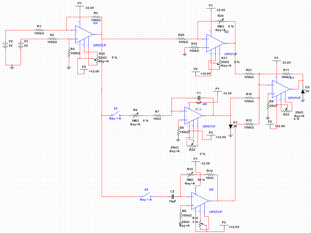
Initially, we did not design a limiting circuit for the integral circuits, which had terrible consequences in practical application. The maximum voltage of OP07 is ±10V. So if not design a limiter, the voltage of the integrated circuit will increase to 10V at the beginning of heating, which is much larger than the ADC range (0-3.3V).
The PID value can be changed by adjusting the potentiometers.
-
Temperature measurement circuit
Pt resistance (Pt 100) was selected to measure the temperature. Pt 100 can convert the temperature signal into an analog voltage signal. And then through A/D conversion, the analog signal can be converted into a digital signal which can be processed by the MCU.
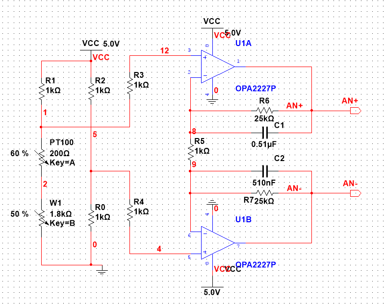
We used a DS18B20 component as standard to calibrate Pt resistance. The calibration curve is as follows:
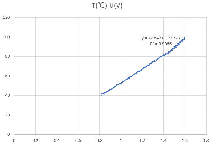
Therefore,
T = 72.643×U-19.723. -
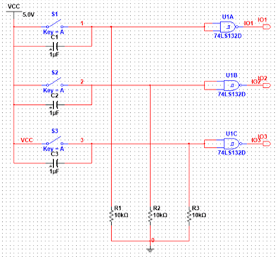
Display and buttons circuits
Choose 74LS139D as a decoder, and four seven-segment digital tubes to show the temperature
XXX.X.Display Buttons 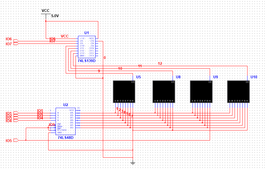
-
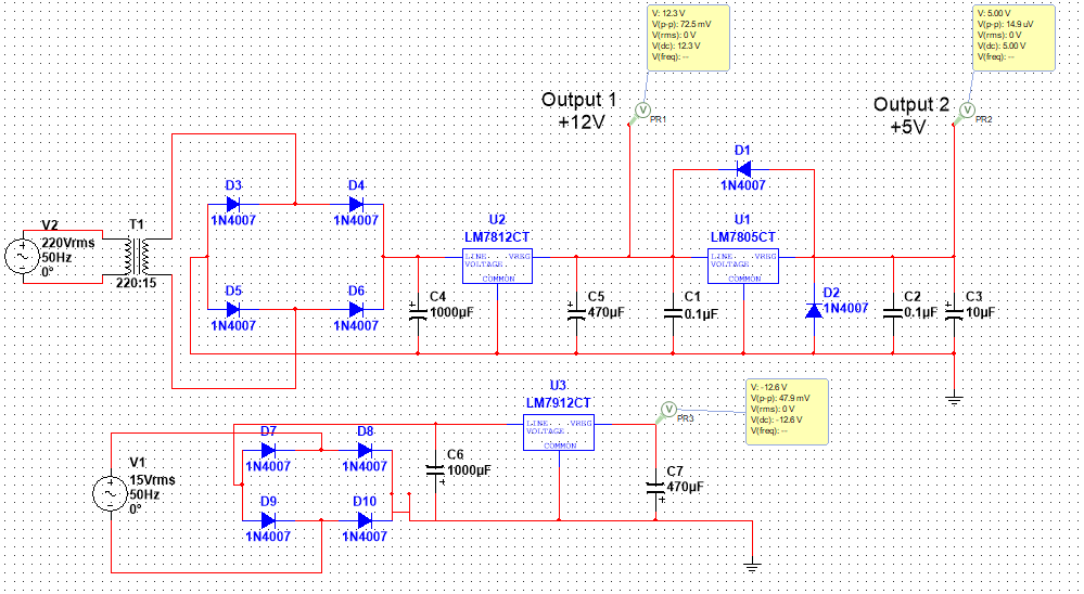
Power circuit
The power supply needs to convert 220V 50Hz AC power into ±12V to supply operation amplifiers, into + 12V to the cooling module, and + 5V to the control circuit.
-
Bluetooth and APP
We selected the HC-08 module, which adopts the serial communication protocol and BLE4.0 to support Android and iOS system.
We used Android Studio to develop an Android App. We used the built-in Bluetooth API to connect the App with the HC-08 module. We completed the function of displaying and controlling the temperature on the cellphone.
-
Healing module
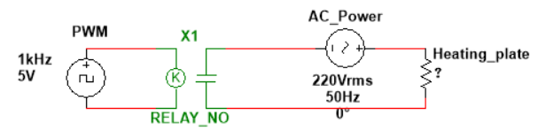
We used a 220V, 600W heating plate to heat the tank. The heating plate was pasted at the bottom to increase the contact area between the heater and the system and make the heating more uniform. After testing, the heating efficiency was 2 ℃/min.
PID control method needs to adjust the power of the heating plate. We connected the relay to the heating circuit and controlled the relay’s switching-on and off by generating PWM wave (5V) through the 555 timer circuit. By changing the duty cycle of the PWM wave, the power of the heating plate can be changed.
-
Cooling module
To cool water quickly, we designed a refrigeration module to speed up the heat dissipation of the system. At first, we used 12V 140W 1275 semiconductor chiller. After testing, we found the cooling effect to be ineffective. Later, we used two fans instead to accelerate the heat dissipation, which significantly accelerated the cooling speed.
-
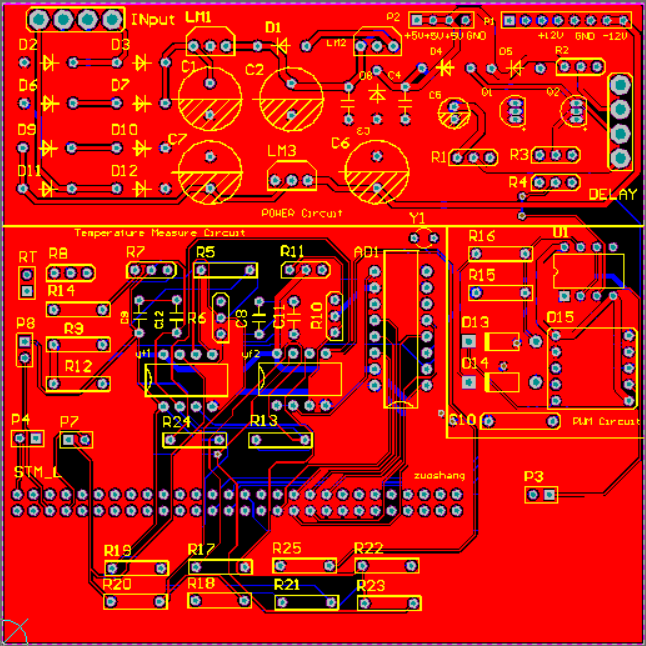
PCB boards
We drew two 10cm*10cm PCB boards to actuate the whole circuits and connect the two boards with an MCU board. The PCB boards are as follows and you can download them from here.
PCB_1 PCB_2 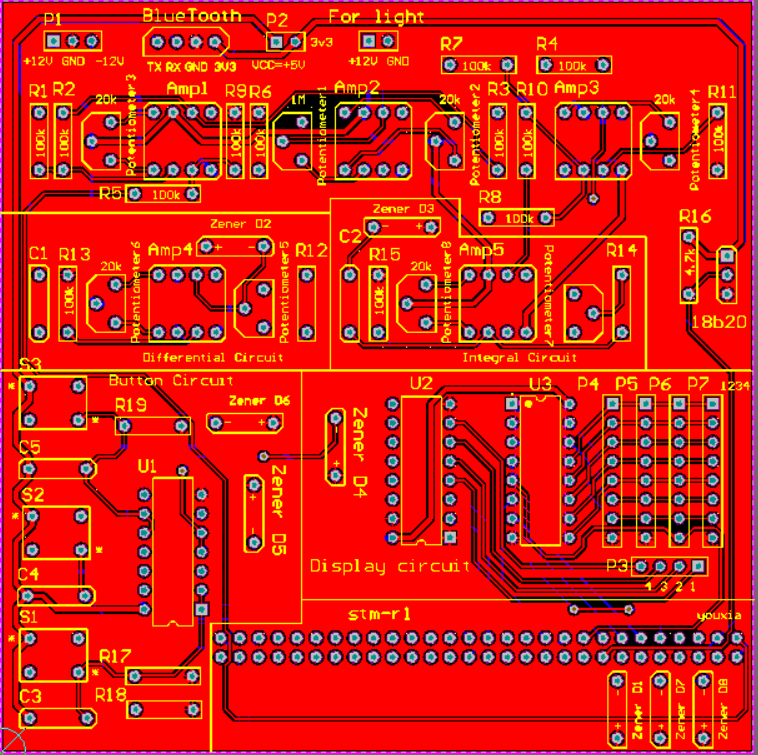
-
Structure
Process Recording
| Stage 1 | Stage 2 |
|---|---|
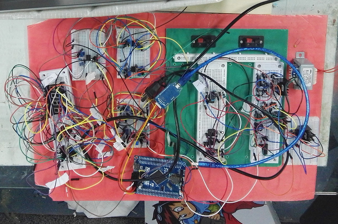 |
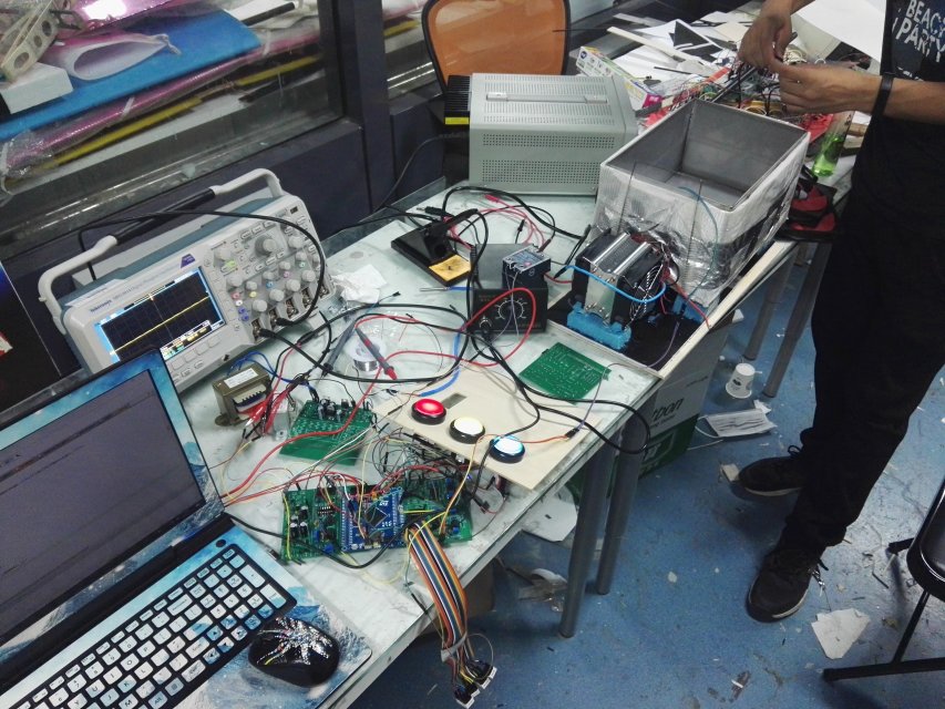 |
| Stage 3 | Stage 4 |
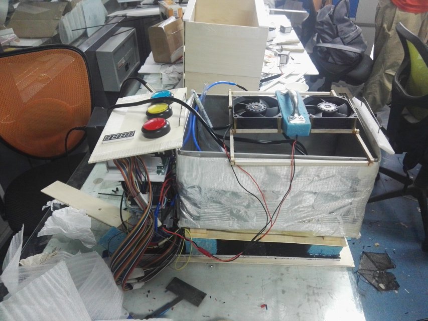 |
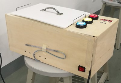 |
Summary
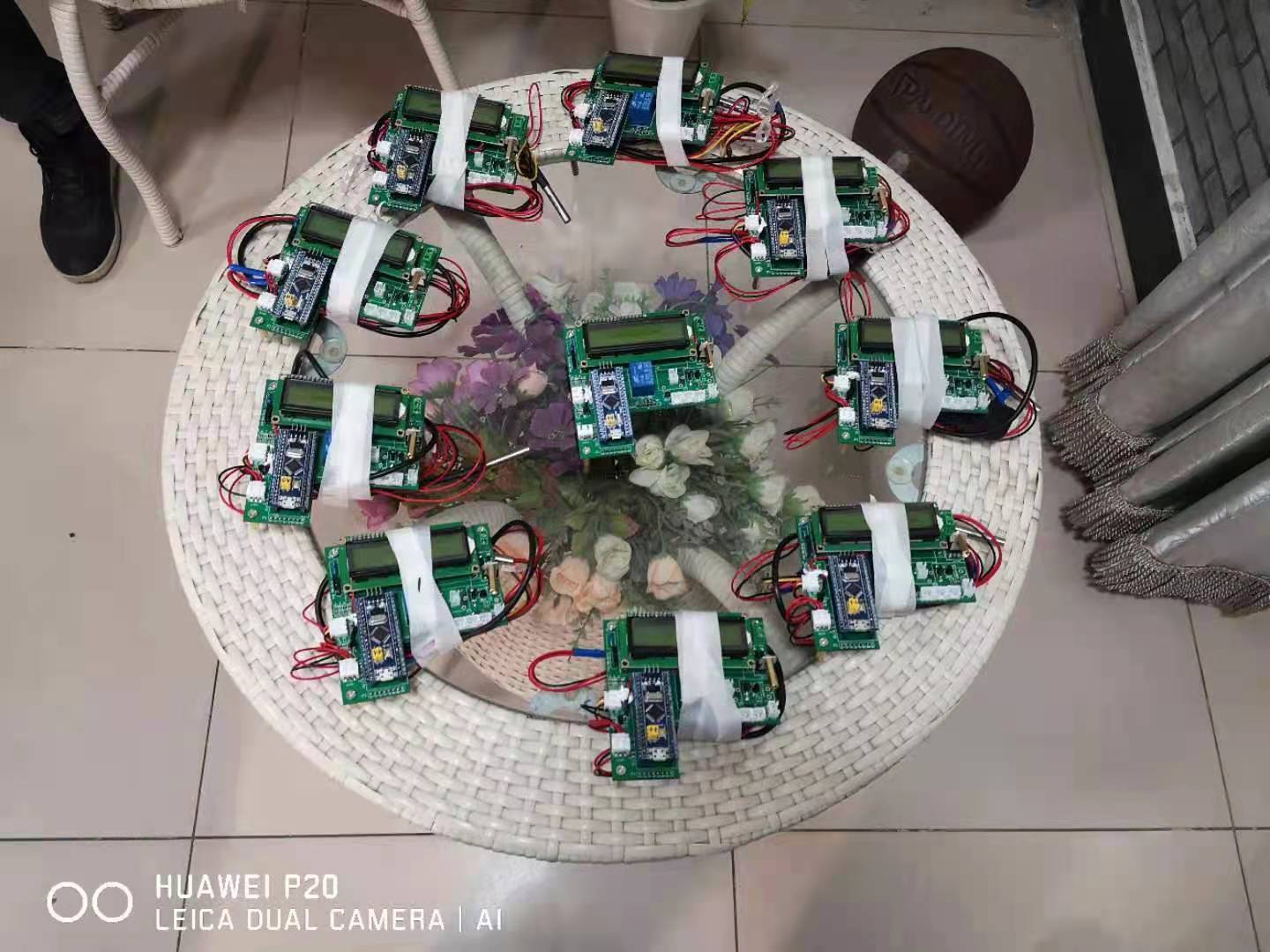
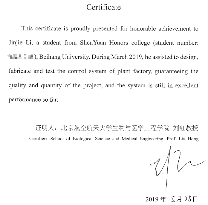
Finally, this project was ranked No.1 in my class! And we were invited by Lunar Palace 1 Lab to design and develop several temperature control systems for plant cultivation.
| Controllers | Certificate |
|---|---|
 |
 |